Monday, September 22, 2008

Shoulders

The last couple of days were spent almost entirely building these:


Here's the idea. The shoulder call for stacks of 8 1/8" pieces with some details and tight tolerances. I bought a sheet of PVC--$50 or so, which is a lot. But I didn't want to do this part in MDF. I think the plastic will give a better, more durable result, especially on the cut edges.

These templates I made by printing up the PDF files in the blueprints to full size. Then I sprayed on some adhesive to 3/4" plywood and laid the plans down on them. The left and right shoulders are mirror images of each other on the cut out details, so I am just going to reverse the template for the other side (I hope I remember to do that when the time comes.)
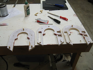
I worked pretty hard to get all of these cuts just right--there's only an 1/8" difference on the edge alignments. I cut the outside straight edges on the table saw with the fence. That let me get good straight cuts and to carefully control the overall width. To get the rounded curve on the top, I screwed the templates together and sanded them on the 90 degree table on the belt sander. That way they will match.

The inside curve--the round part on the top inside of the horseshoes--proved to be hard to cut. I tried the bandsaw, but mine won't cut curves with that tight of a raidus (3.39" diameter, I think.). Finally I built a little circle cutting jig on my router table. I mounted a piece of plywood over the table, put in a small, straight cutting bit, and them measured from the edge of the bit to the pivot point. I put a pin there, and drilled the exact center of my horseshoe template blanks to accept it. Then cutting the circle was clean and had good results. I think I got well within .005" of the club plans. That's good enough for me.

I've spent the last few days routing, chiseling, and filling in the square cutouts on the sides of the horseshoes. My router chewed up the pieces a bit, so you can see some bondo drying in the boxes here. That'll sand up cleanly.

You can also see some dowel pegs mounted on the templates. I got that idea from Vic Franco. Those will accept my PVC sheets, holding them, while I rout around the template with a flush trim bit. I tried a test piece and the results were very clean, and easy. So I cut a stack of blanks--16 for both shoulders and a few extra--and drilled them to match`the three holes for the dowel mounts. When the templates are done, I'll start cutting and stacking pieces.

Booster Covers


If I had any sense, I'd buy the booster covers in resin for $60 and save myself the work and expense. As it is, I spent a good bit more than that getting a couple of router bits and things to build them myself. But clearly, building your own R2 model isn't about having any sense. So I tackled building the booster covers myself. And I enjoyed it for the most part.

I broke the assembly up into pieces that I figured could be easily cut, finished, and machined. So I made up the legs and the main body piece. And I attached the legs at the end using a separate cross piece. This beats trying to build two legs attached by the small piece at the top all at once. I knew that getting inside to make that little router cut would be hard.

I cut blanks for all piece out of 1/2" fiberboard--again this stuff sucks because of the dust it creates and the cancer it causes. If I did this again I think I'd try to do it in plastic--maybe PVC, although that would be costly.


Once I had the blanks glued up (you can get the fiberboard/MDF in thicker sheets, but this is what I had, and the glue up isn't hard once you get the hang of it), it wasn't very hard to first, cut the bevel cut across the top of them--53 degrees I think, and then I set up the router table to trim that bit out of the inside tops of the legs.


Here's the bigger blank that I made for the thicker top assemblies. The thing looks really complicated on the plans, but it all starts with a simple rectangle. I made extras of both here because it's easy when you're tooled up to crank out another one, and I've learned that having a few extras gives you some breathing room and space for mistakes. I find that when I'm doing a new bit like this, my technique get a lot better after the first one.

Next up, I set up the router with an itty bitty round groove bit, set the fence at the right distance, and set up a stop block on the fence to make sure that I got all of them the same length. Then I ran the legs into the router and put this cute little channels into the bottoms. Pretty easy compared to some stuff so far. The channel groove that goes around the legs horizontally above the vertical round grooves isn't hard with the table saw. I checked my main leg assemblies to make sure that the groove on the legs lines up with the groove on them. Vic Franco said that some of the resin booster covers can heat up and warp out of alignment in the curing process and not line up here.


That smear on the left leg, as far as I can tell, is chocolate ice cream from my two year old who was investigating the work bench. I am hoping it will cover over with paint. When he sees the pieces laying around he shouts, "Doo-Deet, Doo-Deet!" It's pretty cute.


Next up I went to work on the top section of the booster covers. Here you can see the funky curve sanded into the top, the side bevels on the curve, and the pockets in the bottom of the block. Here's what I did. The bevel cuts on the top weren't hard. I measured them off according to the plans, and then I cut them with the bandsaw and sanded them (If memory serves.). Then I marked off the curves on the front and back. The curve is beveled--that is, it doesn't cut through at a 90 degree angle from the front face. I think that some people out there have done this part by using a sanding drum on their drill presses and tilting the table on the drill press. That's a simple and elegant solution. As it turns out, the drum on the end of my belt sander was almost exactly the right diameter for this. So I got the curves marked on the front and back and I very slowly sanded away the material until it matched those lines. Not hard.

I made pockets again by cutting all the way through the block with the router table. I think it's a .3" bit or thereabouts and set to .75" depth. Then I cut some replacement blocks to squeeze down into the channel and leave only the two pockets. Next I'll rout the cove out of this bottom face. The plans call for a 5/8" cove. Bits in that size are hard to find. You can order one, but they are $50 or so. I opted for a 1/2" cove bit which is much cheaper and easier to find. Then I think I'll use a 1 1/4" dowel and some sand paper to remove material to get it to spec. If that proves tedious--and I have a very low threshold for hand sanding tedium--I'll bail and leave it at 1/2" diameter, I think. If anyone has better ideas, I'm all ears.


And here's the whole thing so far laid out, along with the little triangular dog house pieces that sit on top. I made those in box form with 1/4" MDF and then cut and sanded them down to size. It'll take some trimming and detail work to get all of this assembled. But it's close to being done.

Outer Feet Details, Finishing, and Primer


Next step was to fashion the little detail panels that mount along with the half moons on the foot shells. Like many of the other details, I could have bought these. But they were really easy to make. Again I used 1/8" expanded cell PVC sheet, cut the pieces, sanded them a bit, and then mounted them with PVC cement. I did some sanding here and there, a little trimming, and filled a few gaps with some putty, then put on a coat of primer. The results are really starting to look like R2. I'm happy with the feet, and I am happy with the difficult task of getting those bottom skirts with the slots done right. I'll be setting these aside for a while until it's time for more painting.


More Foot Details


The half moons for the feet presented a bit of a dilemma. On the plans, and sort of evident in pictures of the real R2, the little square raised panel on the outside of the half moon has a taper so that it gets slimmer towards the top--where the two horizontal slots are. In practice it turned out to be very hard to produce a piece like this in my shop. You'd think it would be easy, but the damn thing is 2" x 2.5" inches, I think, by 1/8" thick at the bottom (going from memory). So that's a pretty little piece to be machining, sanding, grinding, or trimming. I tried several ideas for it. I built a little sanding jig that might let me grind it evenly off. But nothing worked. The plastic I was using melted. I might have been able to do it with fiberboard--but I wanted to make this parts all plastic. And that fiberboard when you sand it puts loads of tiny particles in the air and a big label on it says that the State of California knows it to be carcinogenic. I've breathed enough dangerous fine particulate matter in my life.

So I abandoned the plan to taper it and just used the piece and full thickness all the way up. Maybe that doesn't seem like a big deal, and I don't think it will show much. someone would have to really know what to look for and maybe bust out the calipers to see the problem. But that's the first time on this whole project that I have deliberately punted on some problem because it was too hard--makes me feel like a baby just saying it. "Suck it up, you baby, and MAKE THAT PIECE RIGHT!"

Not really a big deal.

So then I hatched a plan to put those little 1/8" slots across the panels. I set up my router table, ran some test pieces, and just ran the whole half moon piece through, cutting through the edges of the rectangular pattern where it's supposed to be solid. Then I cut some tiny little replacement pieces and glued them back in. You can see them in this picture. But once I've trimmed them, and sanded them a bit, and then painted, they won't show. That "cutting through" trick has made a several little recessed slots on this project much easier than they would have been.

Outer Feet Door Channel: hard


Lots of progress in the last few weeks. Here's a shot of one of the outer feet and the channel that I routed in it. I used a method like I used in the earlier post on the center foot. I must say that thus far, setting up this cut and pulling it off was one of the hardest things I've done. Building the template took a lot of work and a lot of fine tuning, and then actually cutting the channel was rough. The ABS plastic that I had used for the foot shells is really prone to overheat and gum up on any sort of power cutting tools. So getting a clean cut that didn't jump the tracks at all was very tricky. If you look close you can see some hitches in the cut, but it turns out that they cleaned up with some bondo pretty well. So I am content with the result.

After thinking about it a lot, I opted to not cut the panels all the way through. I like the clean smooth look that this leaves instead of having all the alignment problems that reattaching a door would cause. I routed the channel 1/8" deep in 1/4" walls. I may change my mind later, but I can't see that having the door come off is going to be that helpful with the foot motors later in ways that getting to the motors from underneath won't be. I'll try to build the motors with this in mind.

After browsing through the tool store the other day, I realized that there are some small router cutting guides that insert into the bottom plate and that can be used on a template like I have done here. But the difference is that the cutting guides can be used on a template that is much smaller. I made my templates to fit the whole bottom plate of my router. I don't know if using the guides would help. My routing skills and my routing patience are slowly getting better. But I still think it is crumby tool. Too hard to control. It feels like trying to get the Tasmanian devil to behave to cut a perfect straight line.

Monday, September 1, 2008

Access Plates on the Feet


Check this ILM R2 picture: Here's the biggest challenge I have for the last couple of weeks. On all of the feet, there are access panels cut out in trapezoids on the sides.

Some people cut these out with Dremel tools, I guess. I tried and tried but could not find a reliable, or effective way to do this with a Dremel. I guarantee that if you try to freehand this channel, you will not be able to stay in the lines and you'll end up with a butchered piece. So I have been puzzling over how to set up some kind of jig to do this cleanly.

My other challenge was that I don't want to cut all the way through on this. I don't see the need, and too many of these doors look like crap when people try to get them fastened back on. Even the ILM R2 looks like hell.

And while I'm on the subject, have you noticed how completely beat to shit all of these real R2s are? What did they do, kick them down the stairs? I guess that's just the wear and tear of 25 years in some cases and the abuses of a movie set, but jeez. It's making me cringe looking at the chipped paint job, dents, and all. And it kind of seems like they did a crumby job on the paint. I guess there aren't any shots in the movies that scrutinize them as closely as we're doing here.

So here's my clever ( or at least I think it is clever) solution. I carefully drew up the foot side wall on a piece of 1/4" hard board. When the 1/8" bit is in there, the edge of the my router plate is 2.82 inches out. So to rout the channel, I needed a template that was 2.82 inches bigger in all dimensions than the actual size of the channel. So I drew that onto the hardboard around the drawing of the side. Then I cut that out. And notice in this picture that to get the router bit to turn the .625 " radius curve in the corners of the channel, I had to draw a .625 + 2.82" radius curve.


Once I had that bigger trapezoid with curved corners drawn, I cut it out on the bandsaw (to cut an interior piece out like this I just cut through the edge--it won't matter on the finished template. Then I glued that cut out piece onto another piece of hardboard. So there's a lip for the router plate to rest against and when you run the router around it, the cut comes out to be exactly the shape of the channel. Cool huh?

I carefully screwed the template directly onto the sides of the center foot, took a deep breath and checked everything again, and then router out the channel. I'm pretty happy with the results:


There's one flat spot on the lower right corner, but I think I know how to fix that by smoothing out the curve on the template. Given how hard this cut is, I am happy with the results. Now that I know how to do it, I'll cut out a similar template for the channel on the outsides of the outer feet. Once the hole is cut, but before I attach it to another piece of hardboard, I can run a file around the inside edge and make a nice smooth surface for the router plate to glide along. Once these surfaces are sanded, primed, and painted, I think the results will be really nice.

Foot Details

Next I got to work on the details for the feet. Building the half moon pieces for the sides of the feet was a pleasure and went pretty easily. I could have ordered these in resin, but there's no fun in that. And I have a clever solution for you DIY people. These need to be 1 to 1.5 inches thick, roughly. I didn't have any plastic that thick. So I cut out several matching rectangles of 1/4" expanded cell PVC that I had. This stuff works much easier than the ABS. My only worry was the slightly grainy texture that cut edges have. The surface on this stuff is slick and clean, but the core is--as the name suggests--full of tiny bubbles that make it a little rough. These worries turned out to be ill founded, I think. More on that in a second.

So I glued 4 and 6 layer stacks together with some plastic glue I had. It was a watery kind labeled for Acrylic, but the dude at the warehouse assured me that it would work on the PVC too. Turns out it will work, but you really have to flood the surfaces (both of them) to get it to start chemically breaking down the plastic and make for a good bond between the layers.

Once I had those stacks dried, I cut them into a couple of exactly square 7 x 7" pieces. I laid those out with the circles--I can't recall the exact dimension. But I knew that I was going to be slicing my circles into half moons, so I made them bigger to account for the .1" saw blade cut out of the middle. I rough cut those half moons on the bandsaw, and the finished them down to (nearly) perfect semi-circles on the sander. I'm getting better at doing this. And this method rough cutting close on the bandsaw and then finishing on the sander is working well. My sander, as I have said before, can tilt up to 90 degrees so I can put pieces on the table and then run their edges onto the belt, kind of like a jointer.

So I sanded four pieces down to half moons that fit the blueprints. But then how to get then sliced off like wedges of an orange so that they would sit right on the sides of the angled feet? I played around with the tilting table and the fences on my bandsaw and tested several pieces until I got the angle and the cut right, and then sliced them down to make orange wedges.


I don't know if the written description can make sense of it, but the picture shows the result. With many of these steps, you don't really understand the piece or how it works with the R2 overall until you actually get in there are start trying to build it. Then you get intimately familiar with it. So if you are trying to make the half moons, dive in and email me too.

The next trick on these is going to be fashioning a 2" by 2.5" by .125 (or so) rectangle that mounts right on the outside. Look at this picture of an ILM R2:


The tricky part about this rectangle is that it tapers in thickness from .125 (if I remember right) down at the bottom, to almost nothing at the top where it meets the curve and has those two routed slots in it. Making the piece is easy, figuring out a way to cleanly remove material to make the taper has got me stumped. You can't just rub this thing on sandpaper, unless you want to spend an hour on each of 4 pieces. As usual, I want a repeatable, power tool solution to the problem. Right now I am thinking of building some sort of little jig that will allow me to sand or cut the pieces consistently and quickly.

Feet


I have been very busy on the feet lately. There has been some frustration and some success.

I pondered my choice of materials for a long time. As I see it, one could build the feet from aluminum--either welded or JB welded like Dan Baker's, or steel with spot welding, or wood, or plastic. After much back and forth, I settled on plastic. I liked what I saw on Victor Franco's blog about their feet, and the PVC looked like it was good to work with.

When I got to Interstate Plastics, it looked like ABS plastic in 1/4" was as stiff and just as good for my purposes and cheaper, so I bought a sheet of that. It was cheap--maybe $50 --can't remember.

It turns out that ABS--and I should have foreseen this--has a pretty low melting point and it smears and gums up when you saw or sand it if you don't do it just right. Very touchy stuff. If I had really thought it through, I would have seen that because ABS is the same stuff, in thinner sheets, that they use to do vacuum forming. There you heat up a sheet on a frame, force it down over a positive mold, suck the air out and let it cool. My brother's working on a snow trooper this way.

But after some fiddling around, I got the hang of it. And I have to say that all of the trapezoids with compound angles on the feet are really complicated. I botched a few and worked on it for a while, but in the end I got the pretty tight clean joints I wanted.

That's a piece of 3" (inside diameter) PVC cut into quarters that I used for the inside curve that goes under the battery boxes. Also notice that I put the edges of the pieces exposed on the outside--on the channel for the legs for instance, so that I could get to them and sand them easily.

By far, the trickiest parts were getting the bottom skirts right.


Some people seem to have left these off of there R2s, or they have not included the lip that is underneath the strip with the rectangular cutouts, or otherwise altered the plans. I was pretty determined to get this part as close to spec as I could. Eventually, after making piles of scrapped, failed attempts, I cut strips with bevels on both edges, then I carefully glued up a rectangle that was .08 narrower than the tops of the feet. That way, when I glued on the strips with the rectangle cutouts, the pieces would line up with the tops. Sorry I don't have pictures of these steps--my wife cleared the camera. After a lot of sanding and gluing, I was able to more or less accurately join the bottom skirts with the top trapezoids. In the picture you're seeing them before sanding, filling, or repairing. In general I want to get as much done with the saw and the cutting so that I don't have to do a lot of hacking, carving, puttying, and sanding latter. Sanding is dehumanizing, even with my killer 220 volt, 6" x 48" belt sander. I think that with some more work, these will clean up and look nice.