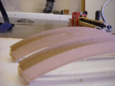
In the beginning, I assumed that I'd want the foot shells to pivot on the legs. It made sense to have him traveling over bumps. But I've rethought that. And I won't be able to pull off any 2-3-2 apparatus. So I am going to build him to be fixed in three leg mode. That left me thinking about a way to join the feet to the legs that was really sturdy and could take some abuse when he rolls around. I was going to put axle pins through the shells into the ankle, but came up with a better idea. I glued up some plywood--stacked to better take the pressure--and cut out these little cleats that will fit in the tracks in the foot shells and around the pointed bottom of the leg. If I had known I would go this route, I would have redrawn the leg patterns to just have this built in. But I'm not going back there at this point. Maybe some day.

Then I carefully drilled some pilot holes up through the cleat and into the legs to accept some hanger bolts. 5/16" by 5 1/2" I think. These are bolts with lag screw threads on one side for wood, and machine threads for a nut and washer on the other.

Yes, that right one is a bit crooked, but that won't matter. Next I lined up these holes to position the foot shell correctly on the leg and then I drilled two holes through the plate inside the groove on the foot shells.

There was some wrangling and cussing, and some redos through all of this, but no more than usual. BTW, I made the template for these little cleats by holding a piece of paper up to the leg (without the foot shell), traced the shape of the leg end, found a level line so that the cleat bottom would be parallel to the floor, and then played around with a mock up shape on the sander until it looked like I wanted. If you are looking for this piece, you can see it. But it's pretty hidden by the leg in the foot shell groove, and once it's primed and painted and finished, it'll look clean and low profile.
I also built some small three sided boxes that would fit up inside the foot shells and wrap around the groove from underneath. My idea was to have the bolts run down from the leg, through the cleat, through the foot shell, and through the inside boxes. Then with some nuts and washers, the whole assembly could be cranked down together. I figured that this layered design would add a lot of rigidity and strength to the whole bottom end. And the boxes can now have some bolts sticking down to bolt on a wheel and motor assembly that can be easily taken off. Pictures help:

In this next picture, the foot shell is flipped upside down and the inside box has been drilled and put inside. Then I drilled these and pushed the whole thing up onto the bolts that come down from the legs. Some nuts and washers snug it all up.

Then end result is not so impressive from the outside. But the joint is really solid now. There's minimal flex or torque. And I will be able to easily mount a wheel assembly onto the boxes inside.

It's really appealing to manufacture an aluminum assembly like Mike Senna and Vic Franco have done on there's. I like that design they've come up with. But I was looking at their materials list and all of the special order aluminum channel, thinking about the expense, and hesitating to use my good wood working tools and blades to cut aluminum. Then it occurred to me that I could probably make a very similar foot motor assembly to theirs out of wood. I'll still have to buy wheels, axles, motors and all of that. But the flexibility of this method is great for me. And it cost me nothing since I used scraps of plywood from around the shop. The hanger bolts cost $4--btw, Orchard Supply Hardware has big ones. Home Depot sucks and does not. Lowe's sucks less, but doesn't have them either.


